Reciprocal Frame Table
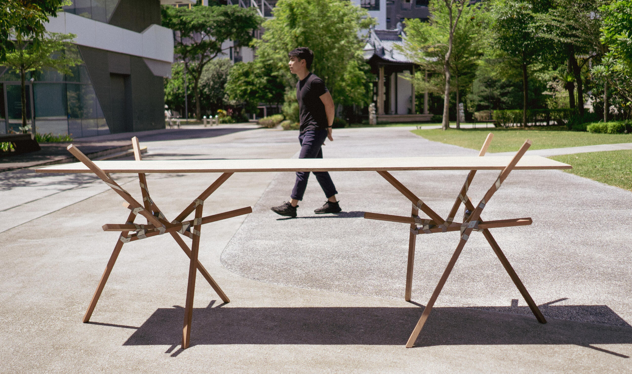
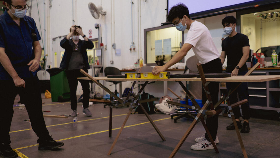
The final project of SUTD's Digital Design & Fabrication and Architectural Structure & Enclosure Design poses a team challenge to design and construct an unconventional table that is structurally sound, using fabrication methods that we have learnt throughout the course of the semester (such as waterjet cutting, laser cutting, woodworking, CNC routing, etc.).
The team chanced upon reciprocal frame structures as a method to replicate a single module many times to create a rigid structure.
The concept then resulted in the use of triangular shaped modules which interlocked with each other. The resulting structure as a ‘tripod’ is fairly rigid, but two provides more balance overall.
Read on to see my process.
prototyping
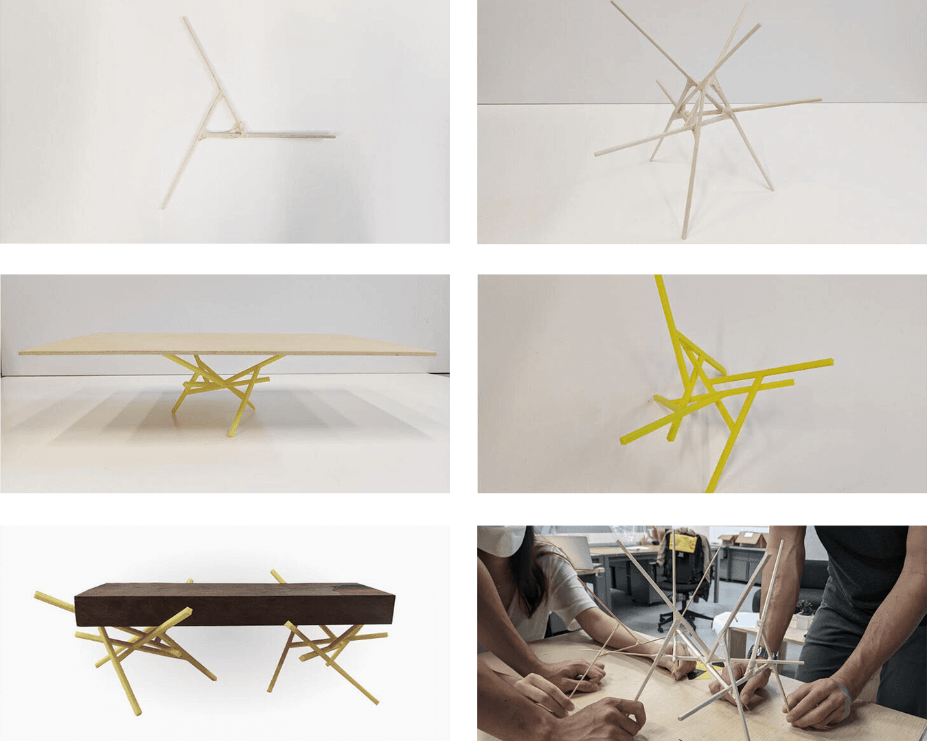
The team began the process by prototyping our idea to achieve a proof of concept. We accomplished this by taping chopsticks together and arranging them such that they lean on each other reciprocally.
We then furthered the testing by 3D printing more precise, to-scale pieces and adding some weight on it.
joinery design
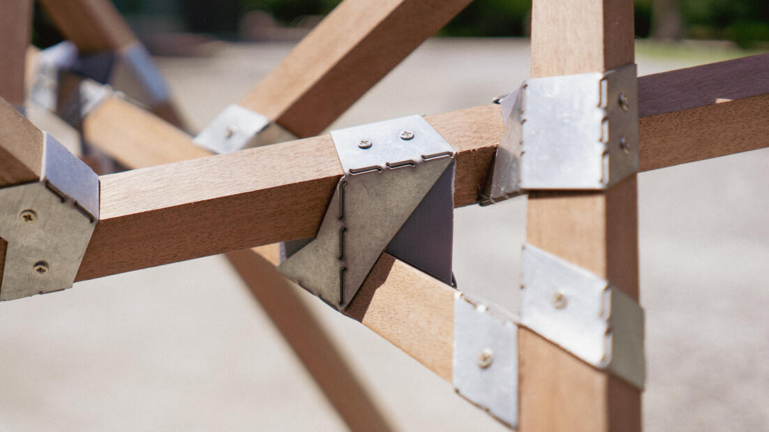
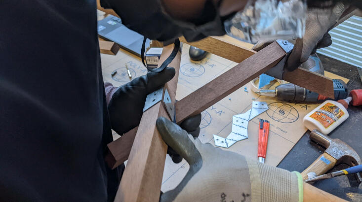
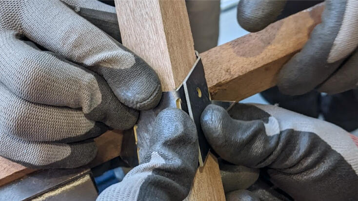
To provide additional structural strength to our table, we designed joints to connect the wooden members where they interfaced with each other.
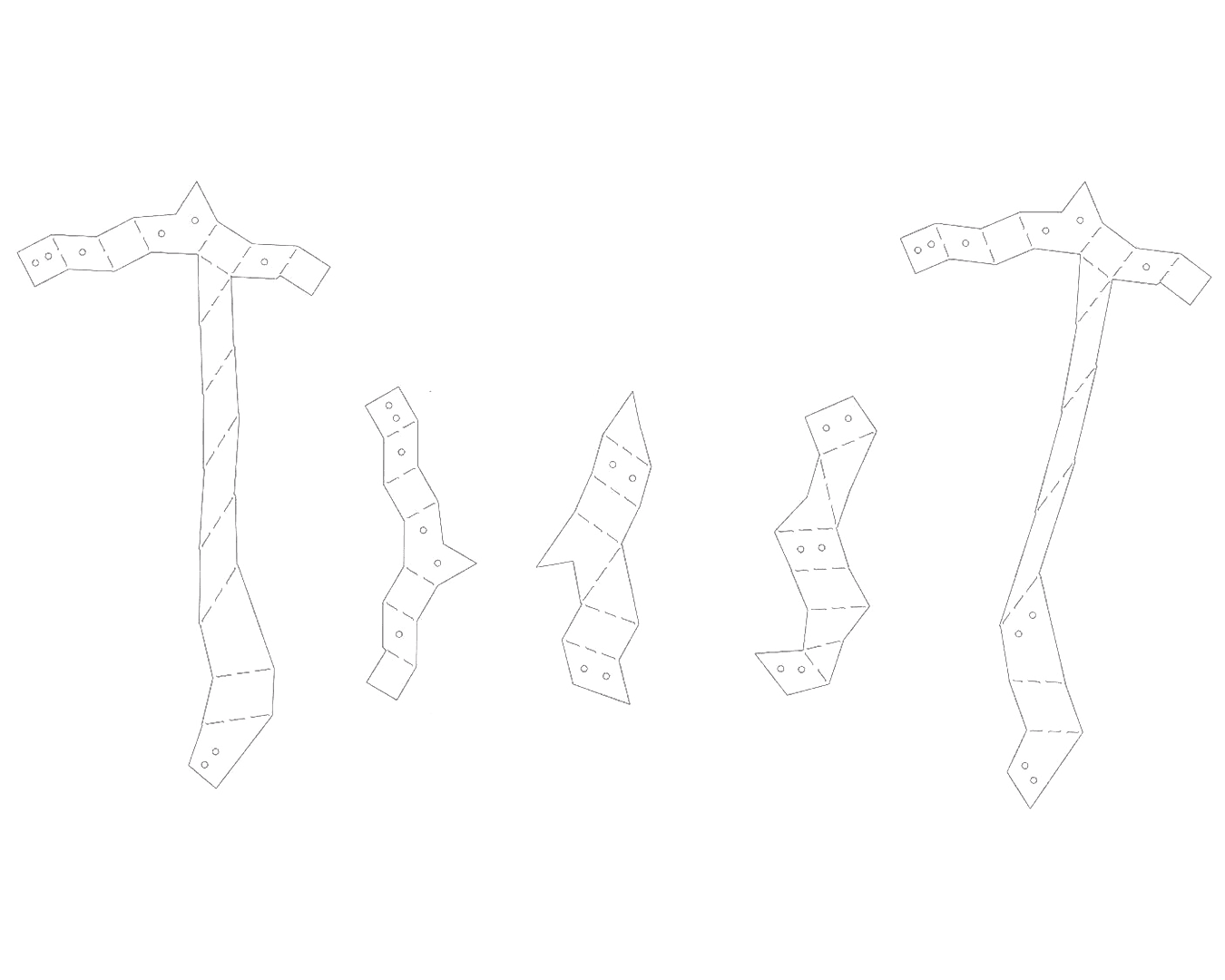
Through the CAD, we have identified five unique joint designs.
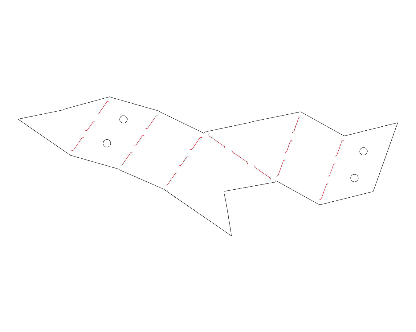
We designed bend lines in detail with a ‘lightning bolt’ design which helps maintain the strength of the bend and constrains the bending of the metal to the same direction with the bend.
The lightning bolt patterns were placed 3mm away from the edges to give sufficient material for bending. It was found in the joint testing that 1mm was too little, and 5mm too much.
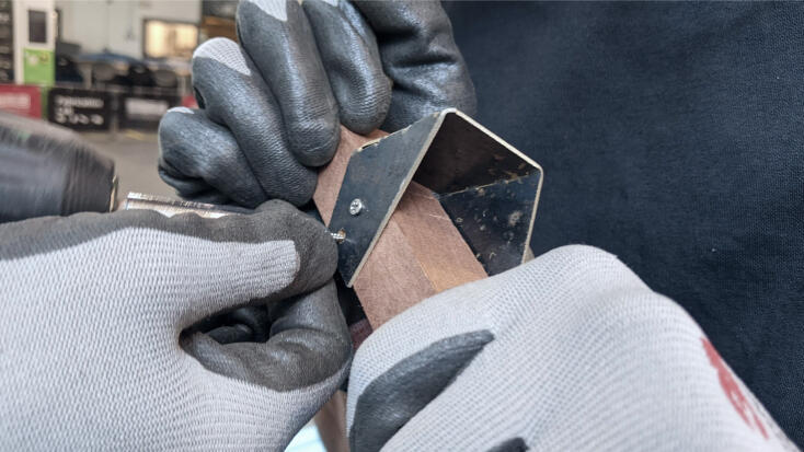
Screw holes were added as mounting points for the metal wraps.
Five unique joinery designs and "lightning bolt" on bend lines
spacers
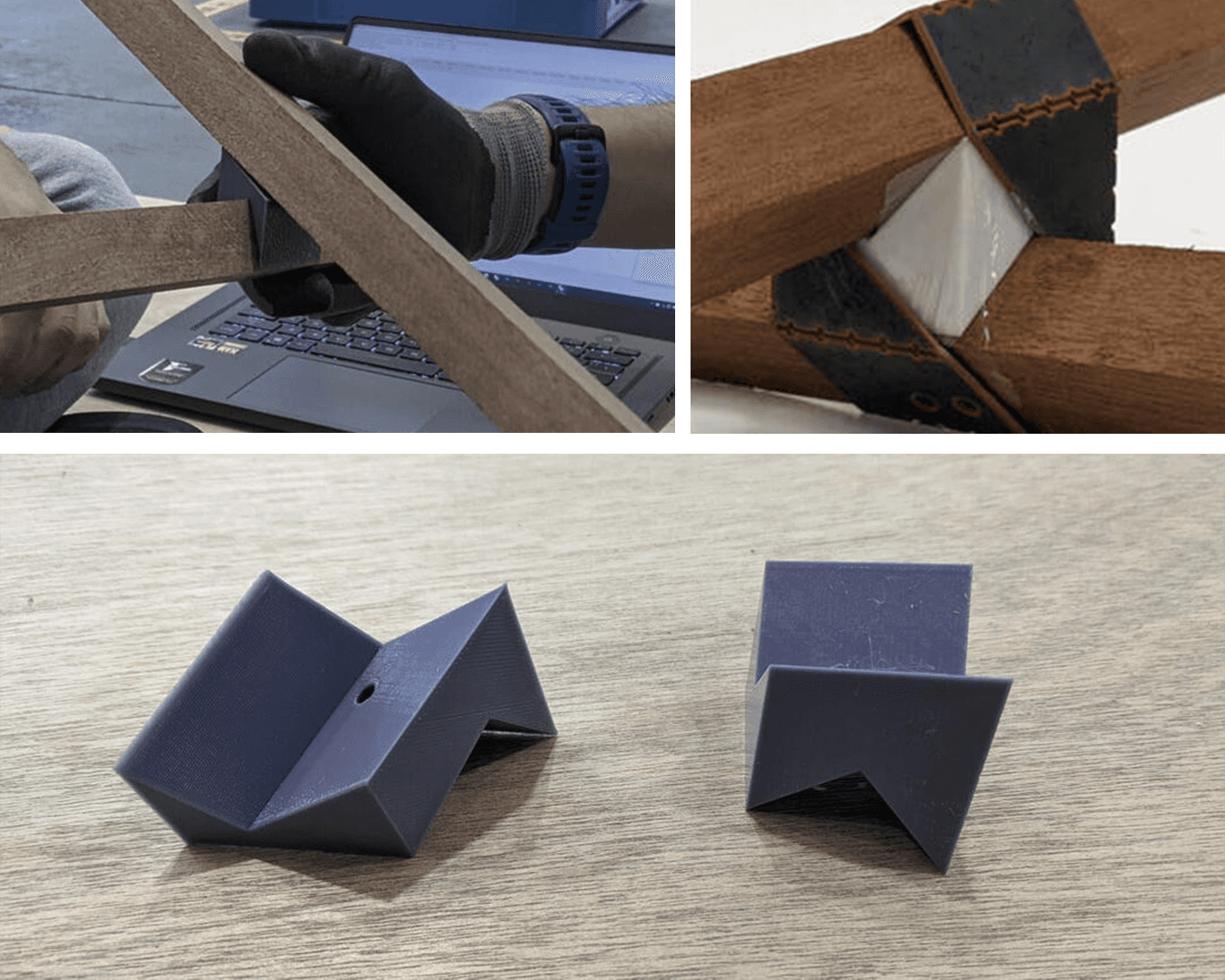
To ensure a snug fit, 3D-printed spacers were introduced to provide additional volume around the wooden members for the metal joints to wrap around correctly, making the structure more rigid by increasing the friction at the contact points between the wooden members.
3D printed spacers between interfacing sections of the wooden members
joint prototyping
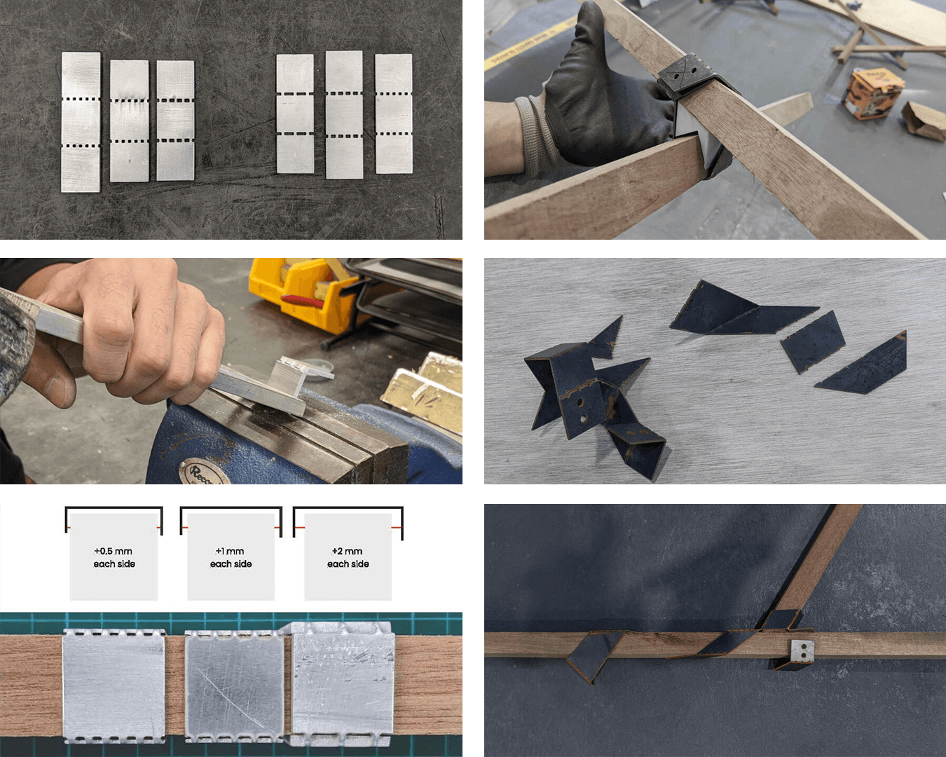
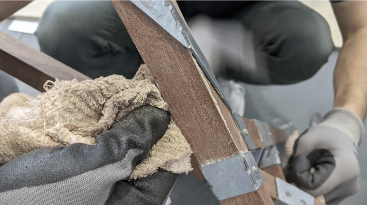
We conducted some prototyping on the joints, as sheet metal can be hard to bend accurately and ensuring that sufficient tolerance is provided for the metal wraps to hug the wood beams is a challenge.
We tested different sized cut-outs of holes, which acted as seams for bending. We then tested sheets with different gap tolerances with 90° bends.
We then tested non-orthogonal bending on our actual wooden members, thereby identifying inaccurate pieces to remodel. Identifying the amount of material to remove was important too, as too much material caused the joints to shatter. Lastly, the amount of tolerance accounted for the bends was critical in ensuring a good fit around the wooden members; insufficient tolerance resulted in erroneous attempts.
sustainable usage
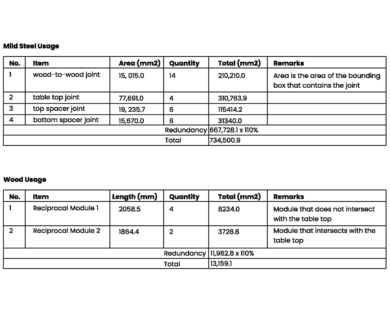
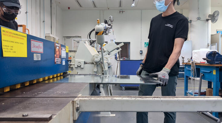
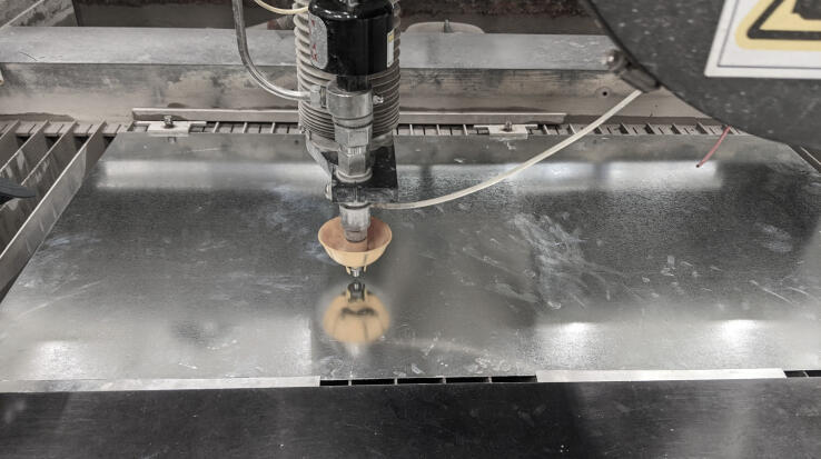
Thorough planning and meticulous calculation was made to ensure sustainable and efficient use of material. The total area of the metal wrap joints was calculated to give a rough indication of the amount of material required to purchase, which came up to a 1200 x 600 x 1 mm sheet of mild steel.
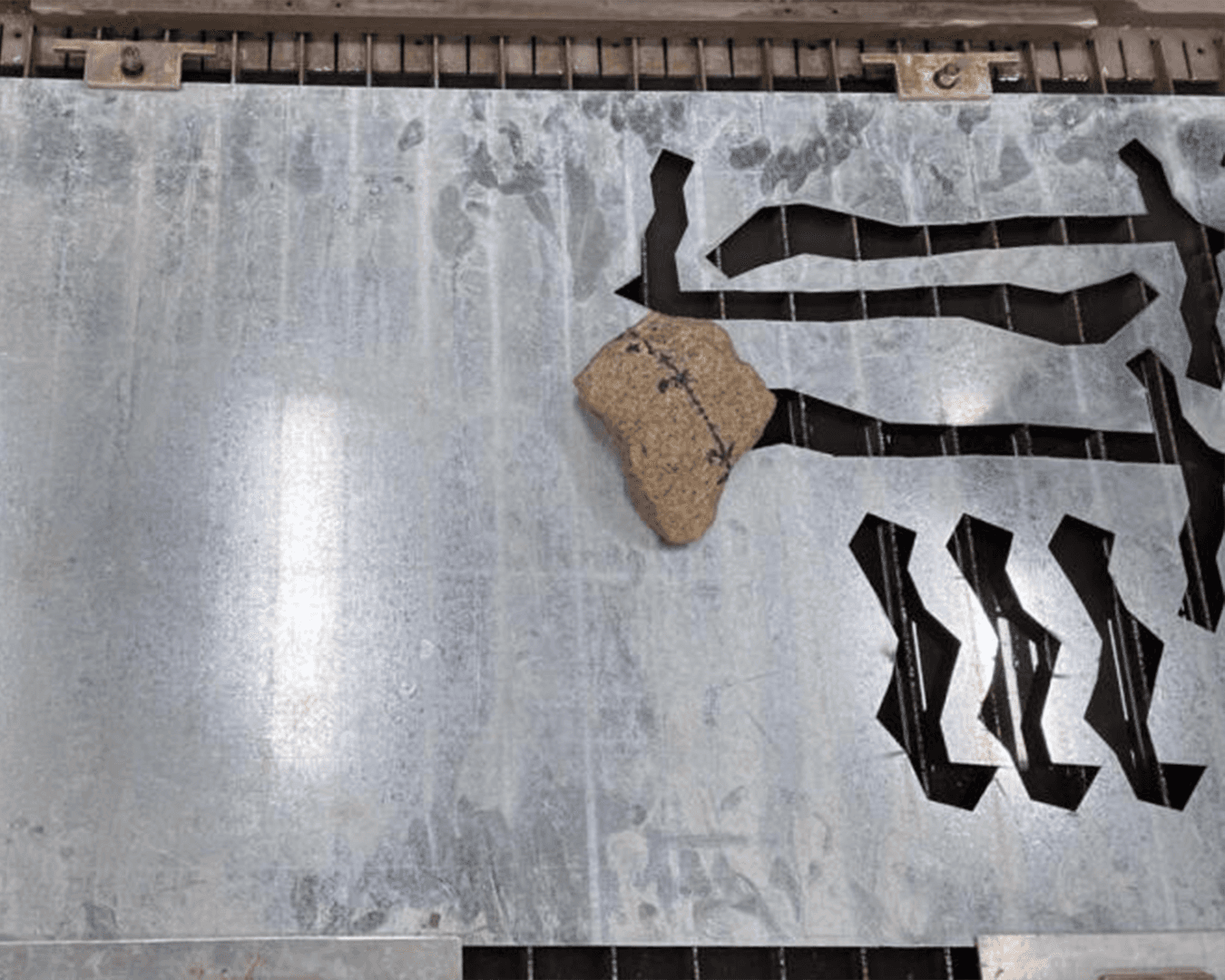
Remaining space left on the steel sheet
load simulation and analysis
Before fabricating the table, we created models through Rhinoceros 3D and Grasshopper Karamba.
We simulated loads at the expected loading points, which should be at the points in contact with the tabletop, since that is where the load is translated to the legs.
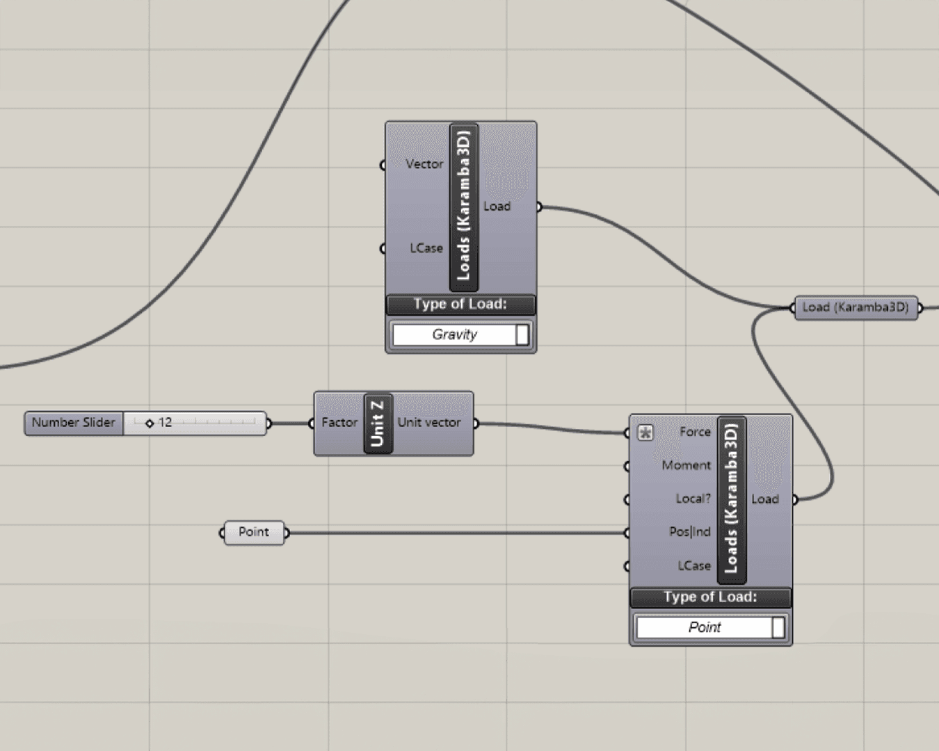
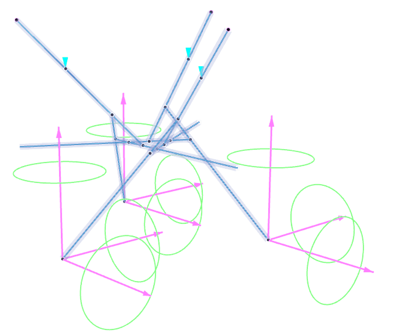
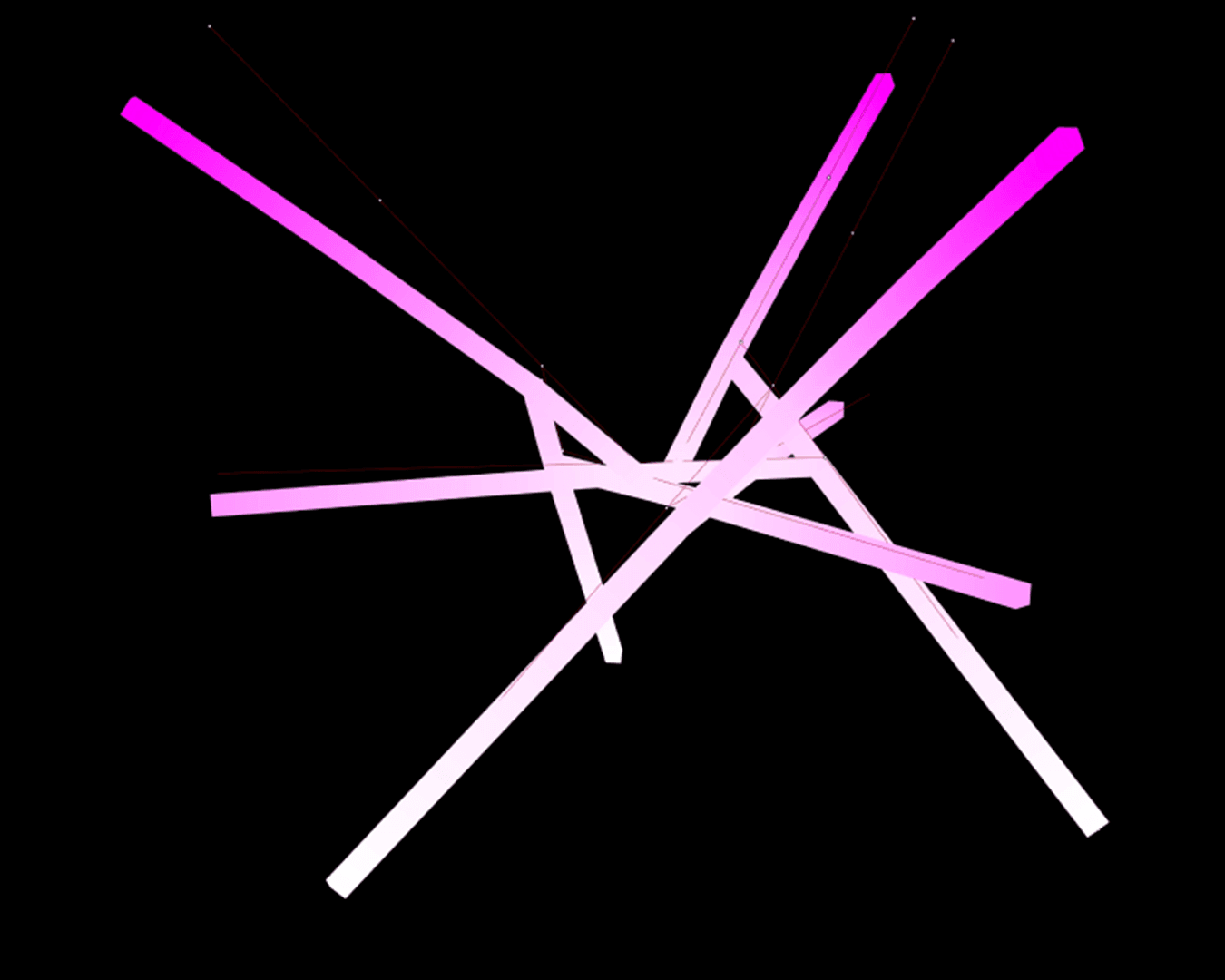
There are 3 contact points (highlighted in the figure below), each of which have been applied a 12kg force, summing up to 36kg, simulating the load of the tabletop and some items placed on it. Gravitational force has also been considered.
Types of loads: Gravity + 12kg load per contact point. Analysis was implemented on one side of the table, since both modules are identical.
utilisation
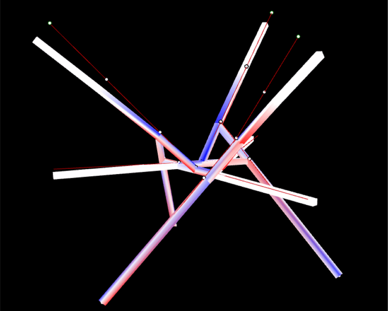
The maximum utilization of 93.7% is reached at a load of 12kg per point, which totals to 36kg for one leg. The table consists of two main legs, hence based on the analysis, the maximum utilization of 93.7% would be reached at 72kg with both legs. This is a considerably safe limit.
Taking into account that the maximum utilization is only at the red parts as shown in the picture while the rest are at comfortable levels, the legs can be further reinforced at those points to make them stronger.
There is some rotational splaying at the base of the legs if the x and y direction is not fixed. This could possibly be addressed by securing the ends together with wire, however, considering the load of the table and the extent of displacement, it was decided that there was no need to do that at the moment.
Displacement (left) and Utilisation mapping (93.7% maximum, -92.5% minimum) (right)
infinite side-scrolling runner
infinite side-scrolling runner
